More Fuel Lines

DSC05089

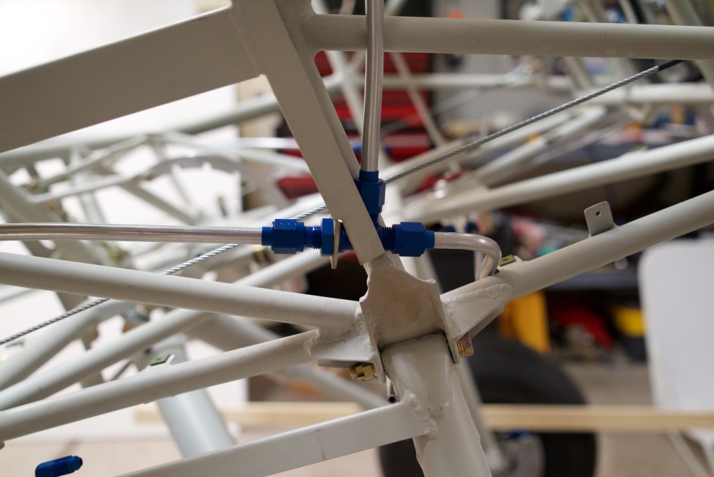
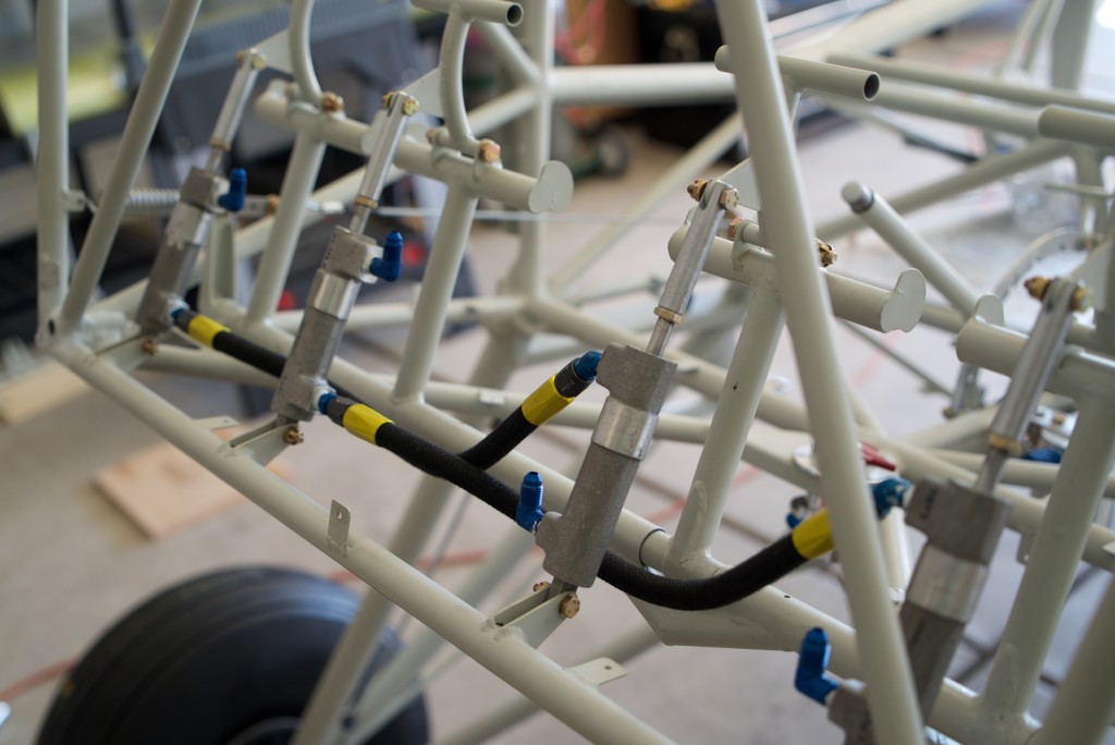
I started working on the fuel T’s that come down from the wing.  Like I mentioned before, all fuel lines should move downhill.  This is not only to promote smooth fuel flow, but also to make sure there are no low areas to trap water that may freeze later.

Bob recommends putting the T in this position as low as possible.  This helps it maintain a down hill slope along the lower door frame.  However, I just couldn’t live with the T going through the door frame bulkhead at the angle of that door frame.  So I carefully bent the lower frame to match the angle of the fuel line coming down the lower door frame.

This allows for a constant downhill flow with no low points.  Mission accomplished!

Floor board attachments

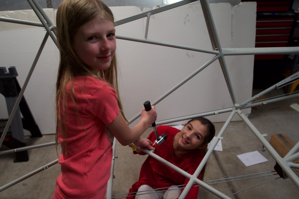
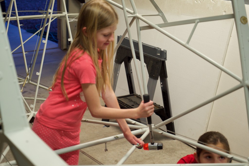
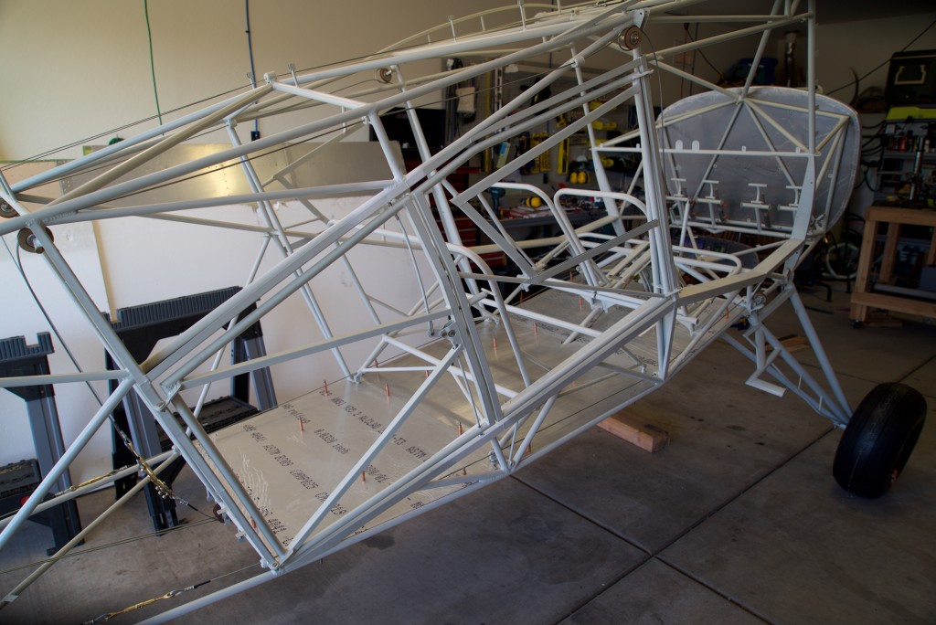
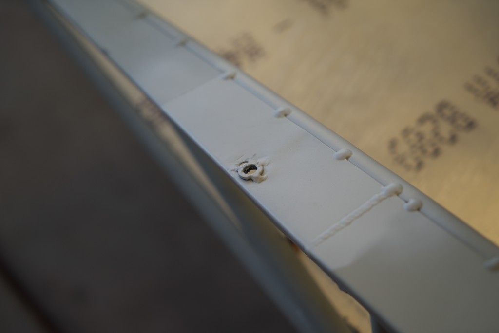
Today the kids and I worked on several odds and ends.  The main thing was the floor board attachments.

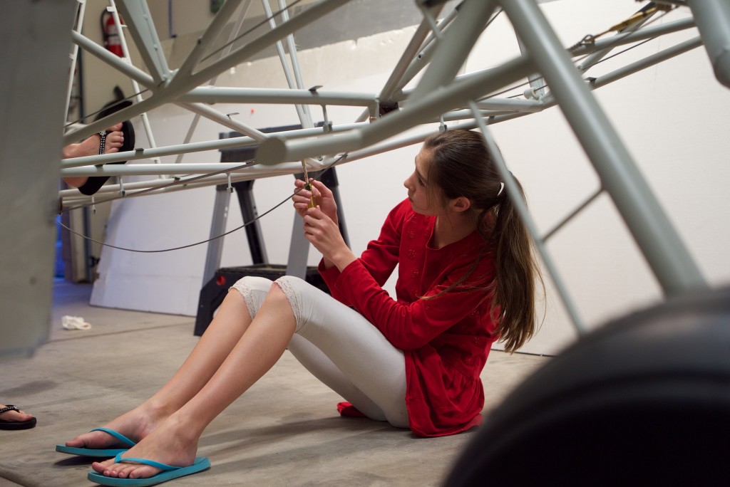
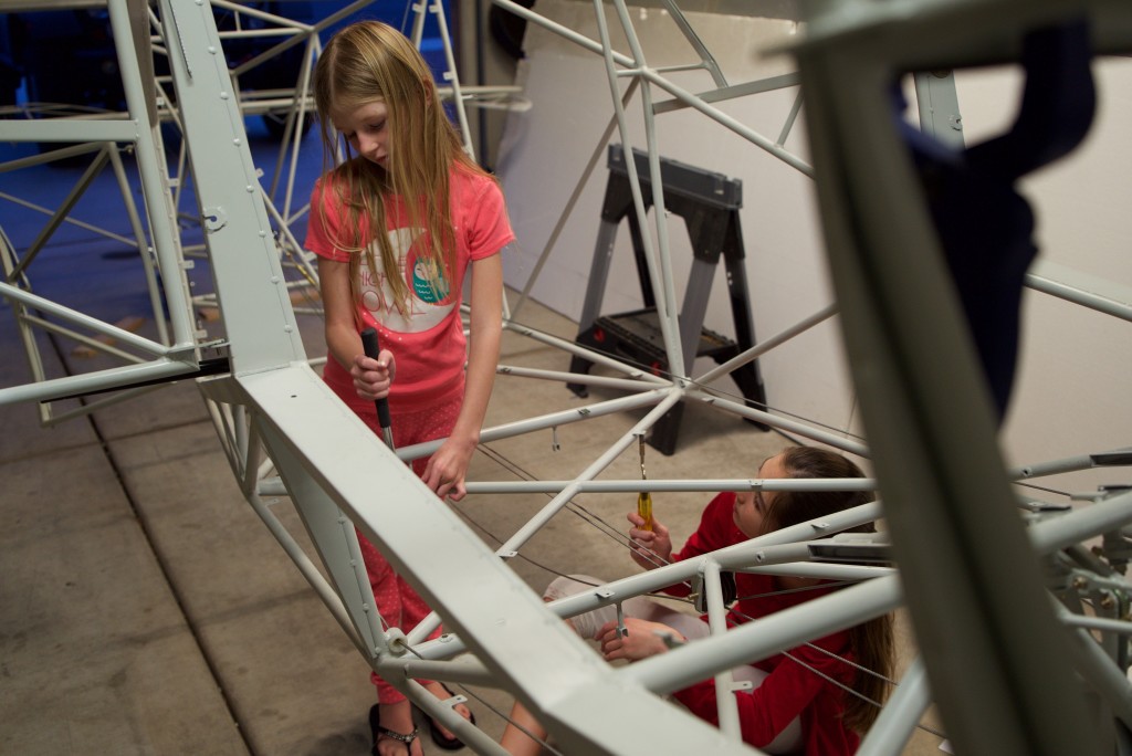
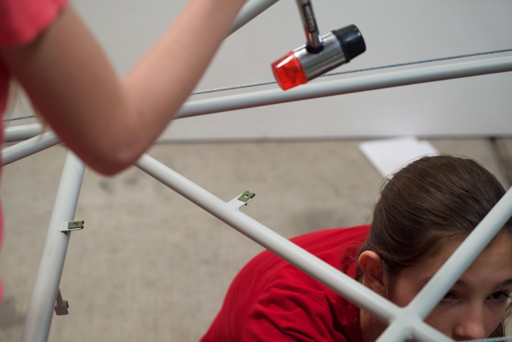
We had quite a little system going.  I would drill the holes, Jessica would debur the floor board and fuselage tabs, then Tori would install the tinnerman nuts.

DSC05083

DSC05084

DSC05085

DSC05086

DSC05087

Cargo Door

DSC05075

One of the really cool things about the Bearhawk are the extremely large cargo doors!

DSC05074

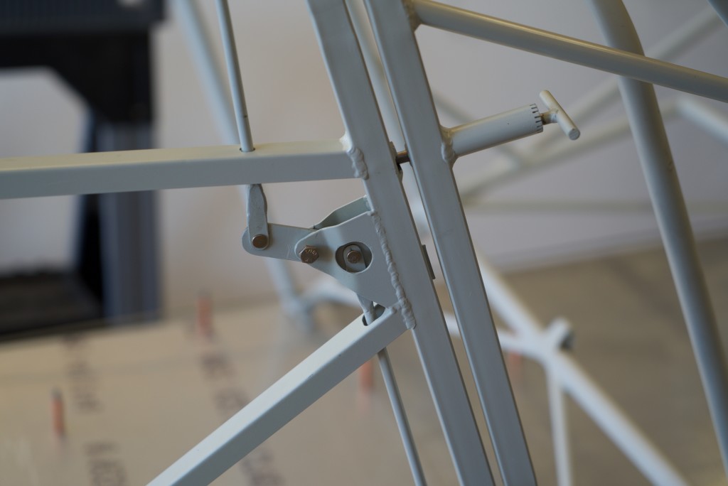
It has a simple but very effective locking mechanism.

DSC05076

The doors when on rather easily however, the holes for the locking mechanism didn’t quite match up.  So I ended up having to remove the old welded washers around the locking holes.  Then I drilled the holes in the correct place and welded on the new doubling washers.  All is good with the world again.

Gascolator and Fuel Valve

DSC05072

I’ve given the fuel system substantial thought.  Several hours have been spent just pondering it!  There are recommended ways and “rules” for everything to be done.  From what I’ve seen there are plenty of people that depart from the rules and recommended ways!  The fuel system is rather important so I intend to do it right.

The first “rule” I had to contend with was that the gascolator has to be the lowest point in the fuel system.  This means it has to be behind the fuel valve.  However, if you put the fuel valve where the designer recommends it, there’s not room for the gascolator at the same location.

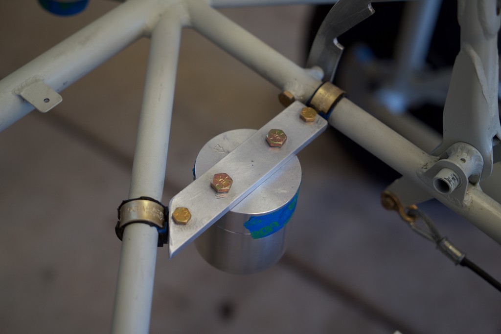
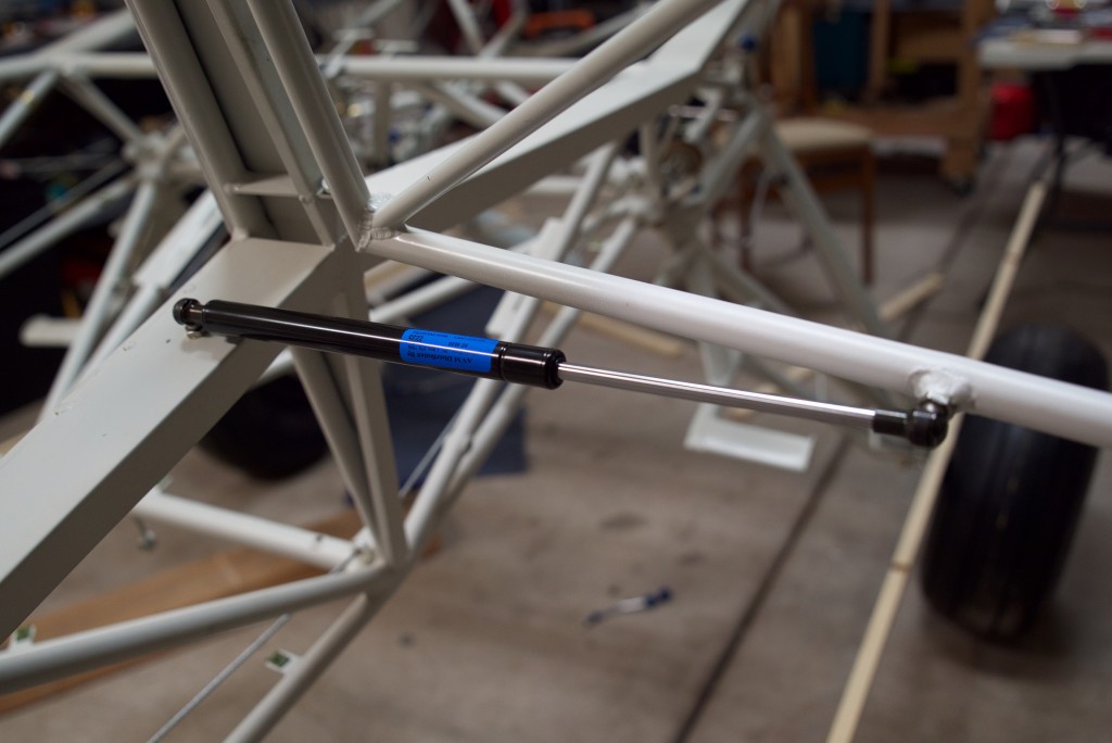
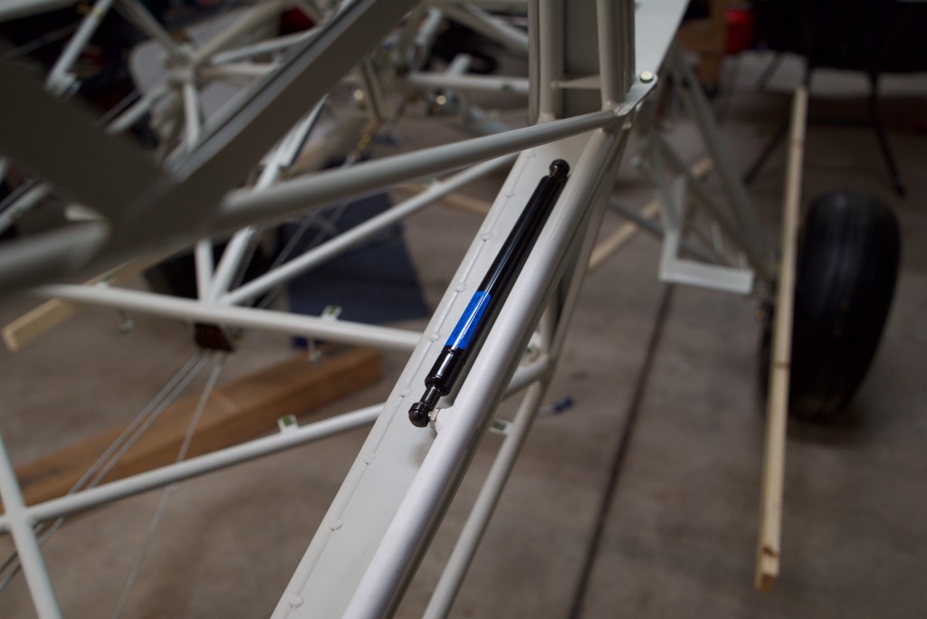
After conferring with Mark Goldberg, I decided to fashion a mount for it near the flap handle.  You can see in this picture my first rendition of this idea.  I later built it with much thiner aluminum and moved the gascolator right to allow for line clearance.
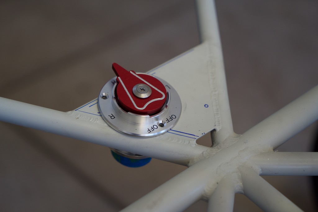
 

DSC05073

You might be wondering why this fuel valve is backwards.  I’ll get to that in a minute.

I settled on a SPRL fuel valve.  It’s very smooth in operation and has positive locking positions that negate the need for a kick guard.  It’s been recommended for Bearhawks and doesn’t have the “out” line exiting vertically like the Andair valves do.  However, the SPRL “out” line exits forward.  That might be fine for a nose dragger but not for a taildragger.

Which brings me to the second “rule” that I had to contend with – all fuel lines run down hill to the gascolator.  Some people have just run a line out the front and back around the the gascolator but this breaks that rule.  So I decided to mount the fuel valve backwards so the line exits at the rear and continues to flow downhill.  I’ll have to figure a way to fix the labels, but I figured having a “correct” fuel system is more important than having to fix labels.
Flap Cables

DSC05067

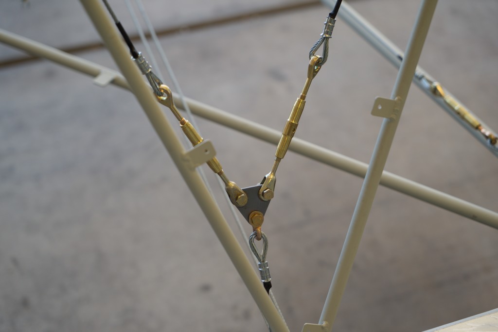
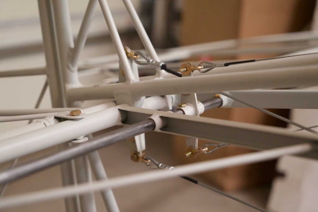
Today I installed the remainder of the flap control cables.  This picture is at the rear of the baggage area.  A single cable runs underneath to this triangle.  From there each cable goes up to pulleys then along the top of the fuselage to the wing to activate the flaps.

The triangle has 3/16″ holes in it but the turnbuckles were 1/4″.  Some people had just enlarged the two holes to 1/4″.  I decided to bush the turnbuckles down to 3/16″ instead.  This is the way it was designed to be done since the original holes were 3/16″ and the kit came with bushing material.

Rudder Cables

DSC05079

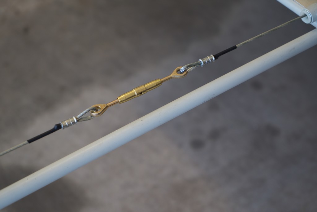
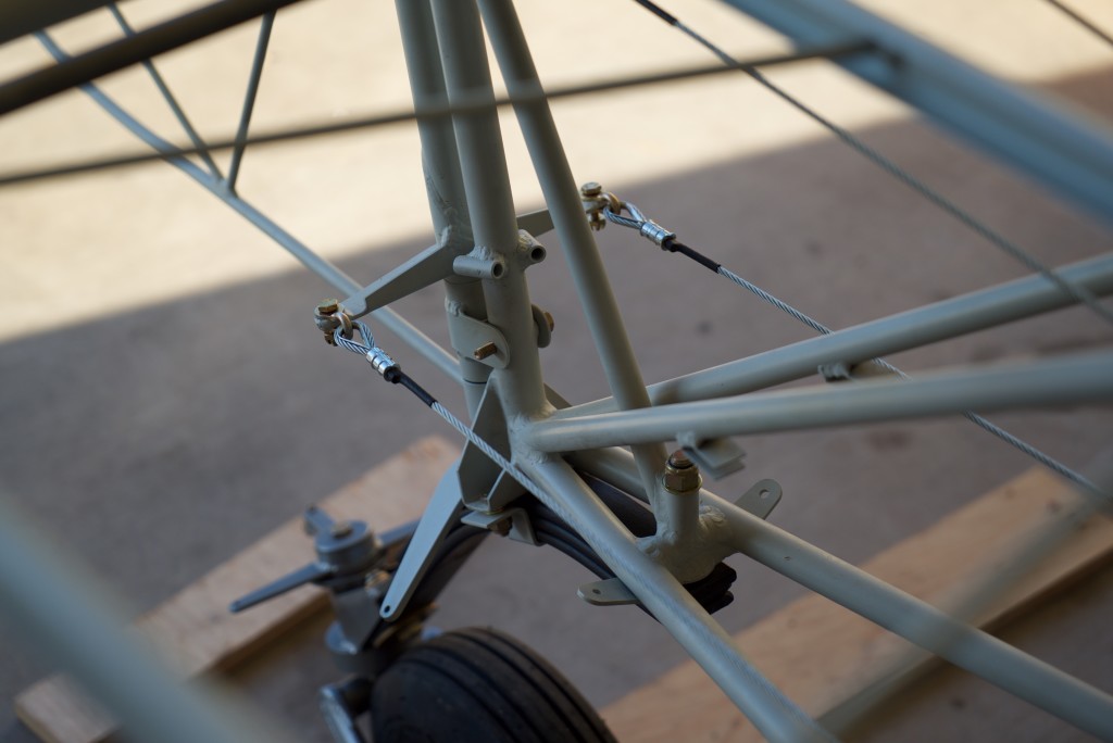
Today I installed the rudder cables.  The system  can be installed without turnbuckles, but I’ve always been particular about rudder control and feel.  So I decided to install the turn buckles so it can be adjusted exactly right.


DSC05077

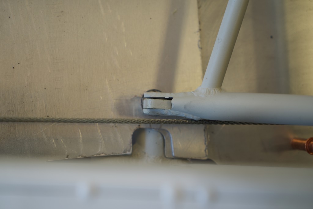
The rudder cables contact the rear seat.  This is because the fairleads at this station were omitted on my kit.  I contacted Mark about this.  He said that Bob visited the factory and didn’t think they were needed.  Well…. on my kit they were needed.  So I have a few options.  I’ll probably just weld new fairleads into position.


DSC05066

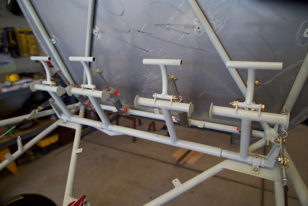
Here you can see the rudder pedals connected with the springs and cables.  I’ve been unable to find the suggested 1″ springs anywhere.  I’ve settled on using these 3/4″ springs in the meantime.  I’m still considering thicker or thinner springs.


DSC05069

Control Cables

DSC05070

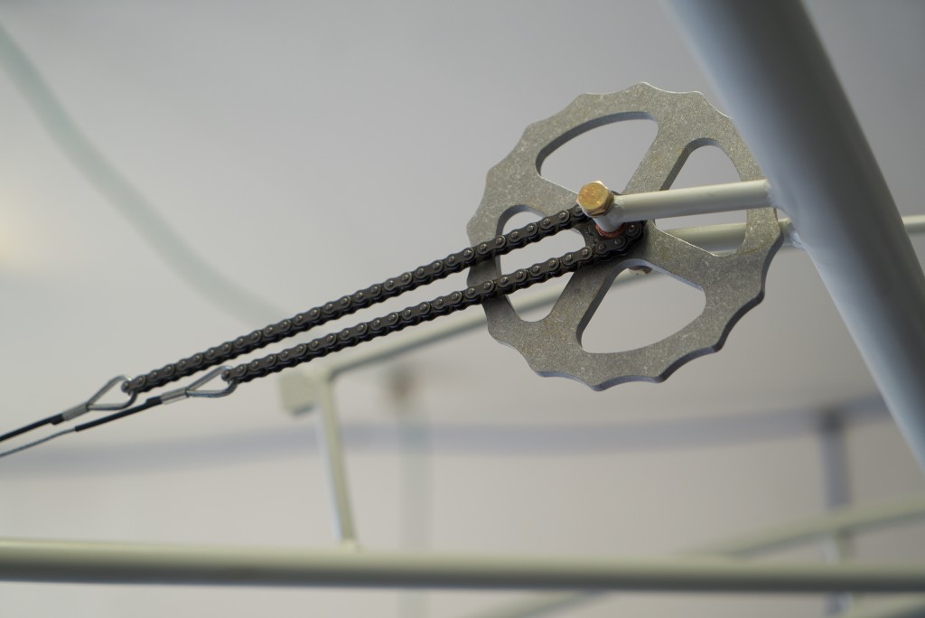
The trim system required some bronze washers.  I couldn’t find theses locally or at Aircraft Spruce but I did find them on Amazon!  The chain needed a little bit of persuasion to accept the cables.  I had to remove one link from each side.

DSC05060

Here are the elevator and trim control cables.  The swaging process has been rather enjoyable. It’s cool to have the elevators actually work with the control stick!