Fuel flow test

The Bearhawk fuel system is gravity fed with no fuel pumps.  As I previously mentioned I took great care to make sure there were no 90 degree turns in the fuel lines and that everything went smoothly continuously downhill.  So now is the moment of truth.  How good did I do?

The fuel flow testing was done in accordance with the 14 CFR 23.955. Here are the criteria:

1. Place the aircraft with a nose high attitude that exceeds its maximum climb angle plus 5 degrees (the 5 degrees is the assumed angle of attack).

2. Put minimal fuel in the tanks.

3. Take the fuel supply hose loose at the carburetor and prop it up at the same level as the carburetor inlet.

4. The measured fuel flow should be at least 150% (125% if you have a fuel pump system) of the takeoff fuel consumption for the engine.

Russ Erb did a lot of the calculating on this. According to his numbers the fuselage should be placed at about 19 degrees nose up attitude.


So what is 150% of takeoff fuel consumption?  My O-540 has a BSCF of .50 at full take off power.  So the math looks like this:

.50 BSFC x 260 HP / 6 = 21.6 GPH x 150% = 32.5 GPH

So the engine for this Bearhawk drinks 21.6 gallons per hour at full takeoff power.  The FAA wants to see fuel flow rates in excess of 150% of that.  So 32.5 is our goal.

To start with, we put 2.5 gallons in each tank and did a quick fuel flow test in a 3 point attitude.  Wow!  42.0 GPH looks promising!  Now on to the real fuel flow test. (disregard the gallons remaining. I don’t have electronic fuel sensors and that was just a default value)

My brother and I pushed my Bearhawk to a nearby drainage ditch to put the tail in so we could attain the required 19 degrees pitch up attitude.  Next we place 2.5 gallons of fuel in each tank, purged the system of air and attached gallon water jug to catch the fuel from the fuel line at the carburetor.

I flipped the fuel selector to both and timed for exactly 60 seconds at which point I flipped the fuel selector to off.

We did the procedure 5 times. Each time it was nearly the same, but we averaged the results just to be sure.

The average came in at 3 lbs 6 oz after 1 minute.  That comes out to 3.38 lbs.  So the math follows that 3.38 lbs x 60 minutes = 202.8 lbs.  202.8 lbs / 6 lbs per gallon = 33.8 GPH.

32.5 GPH was the goal.  33.8 GPH was our result.

So, at 5 degrees above max pitch our gravity fed fuel system is able to supply 156% of required fuel flow at max power at sea level.  Talk about overkill!!  But the most important thing is that it exceeds FAA guidance.

Covering Ailerons and flaps

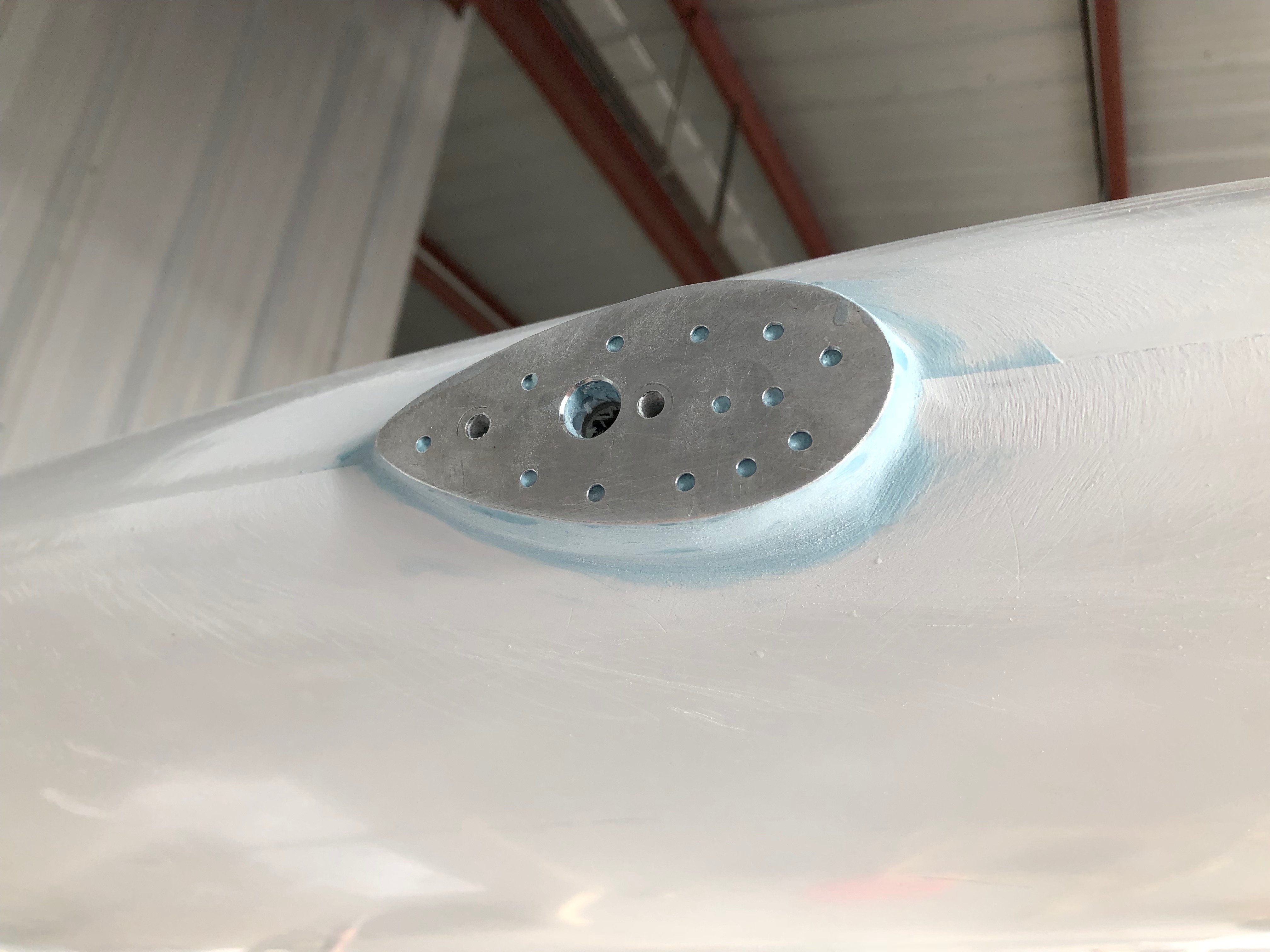
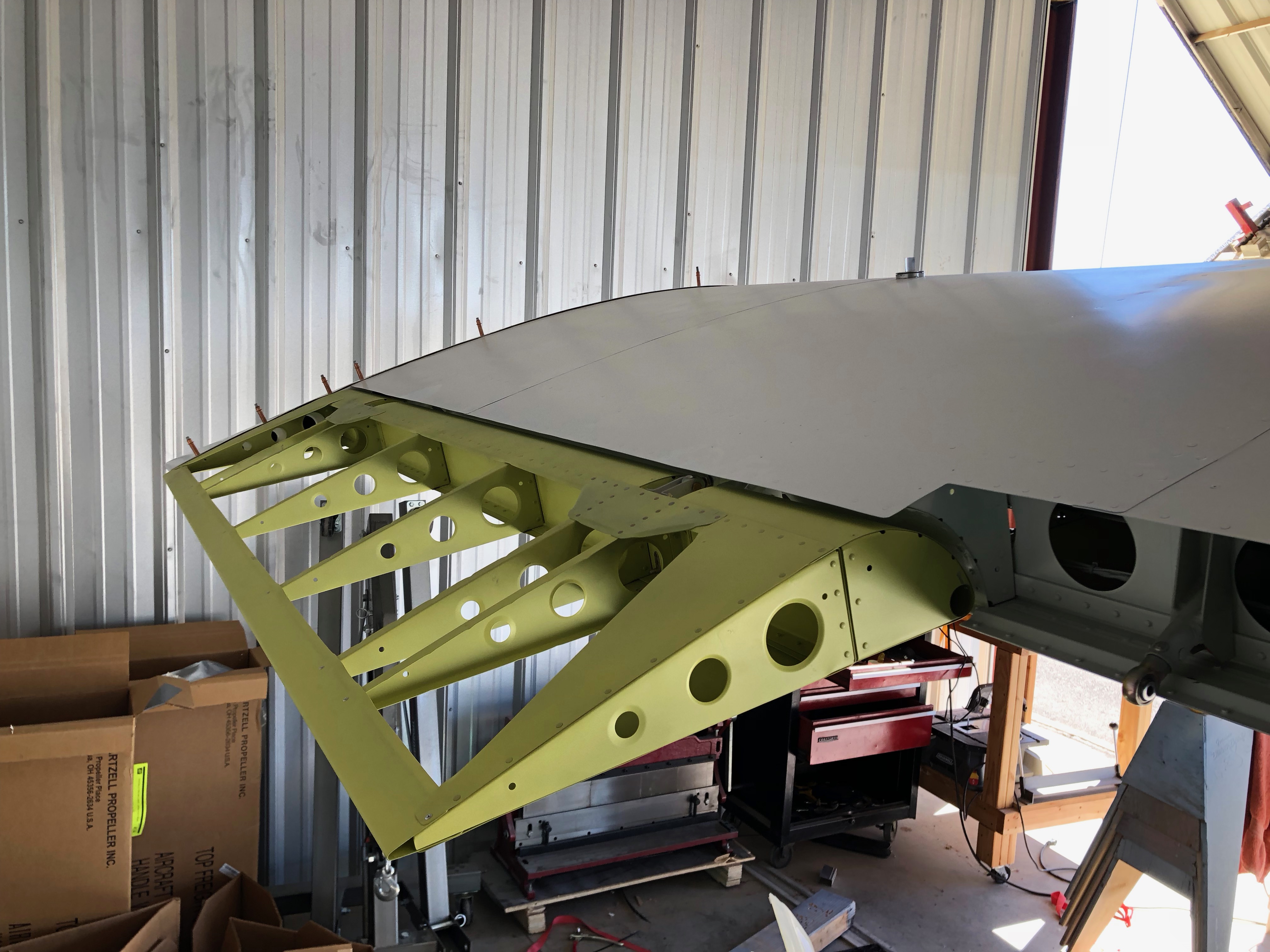
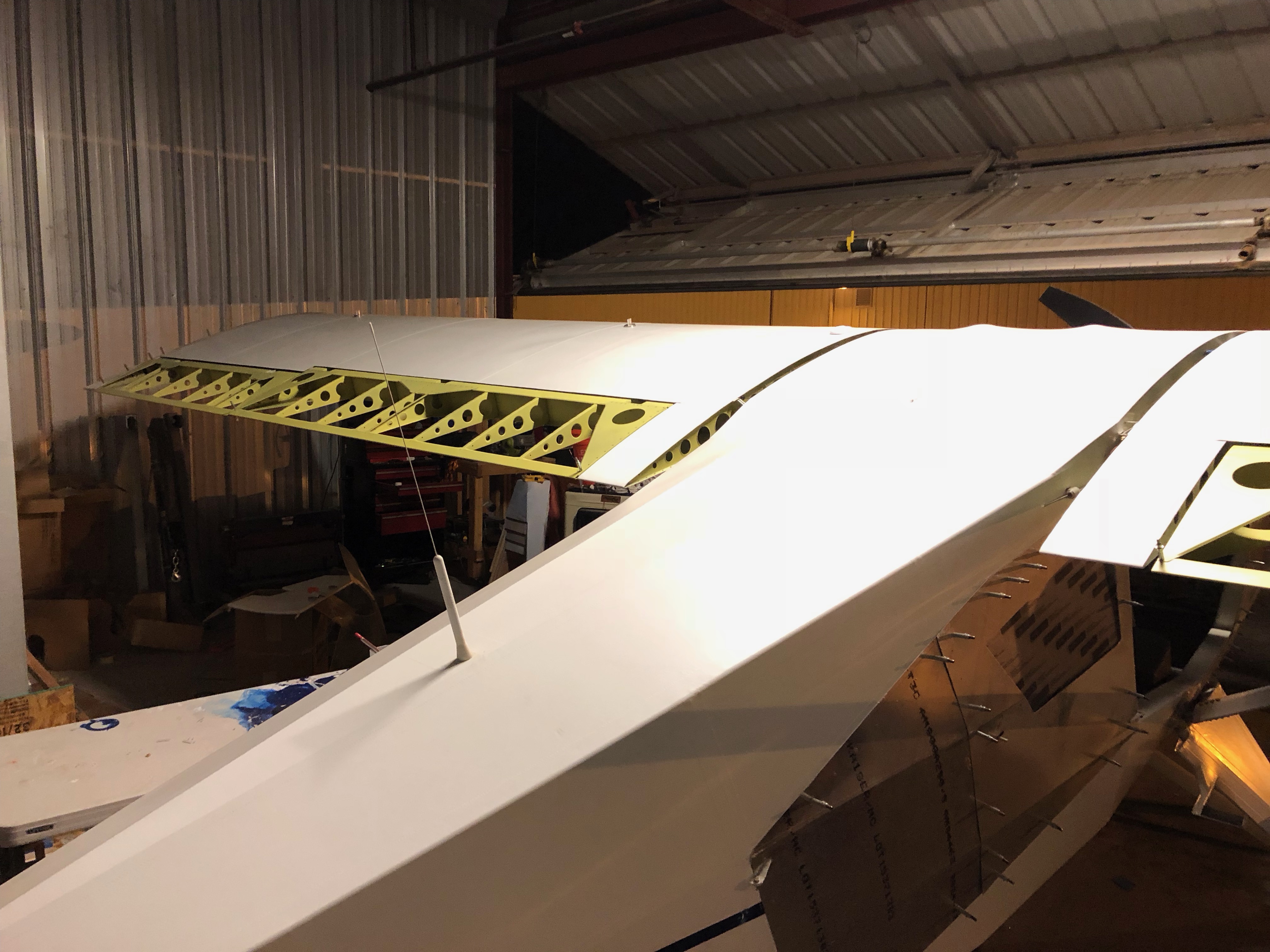
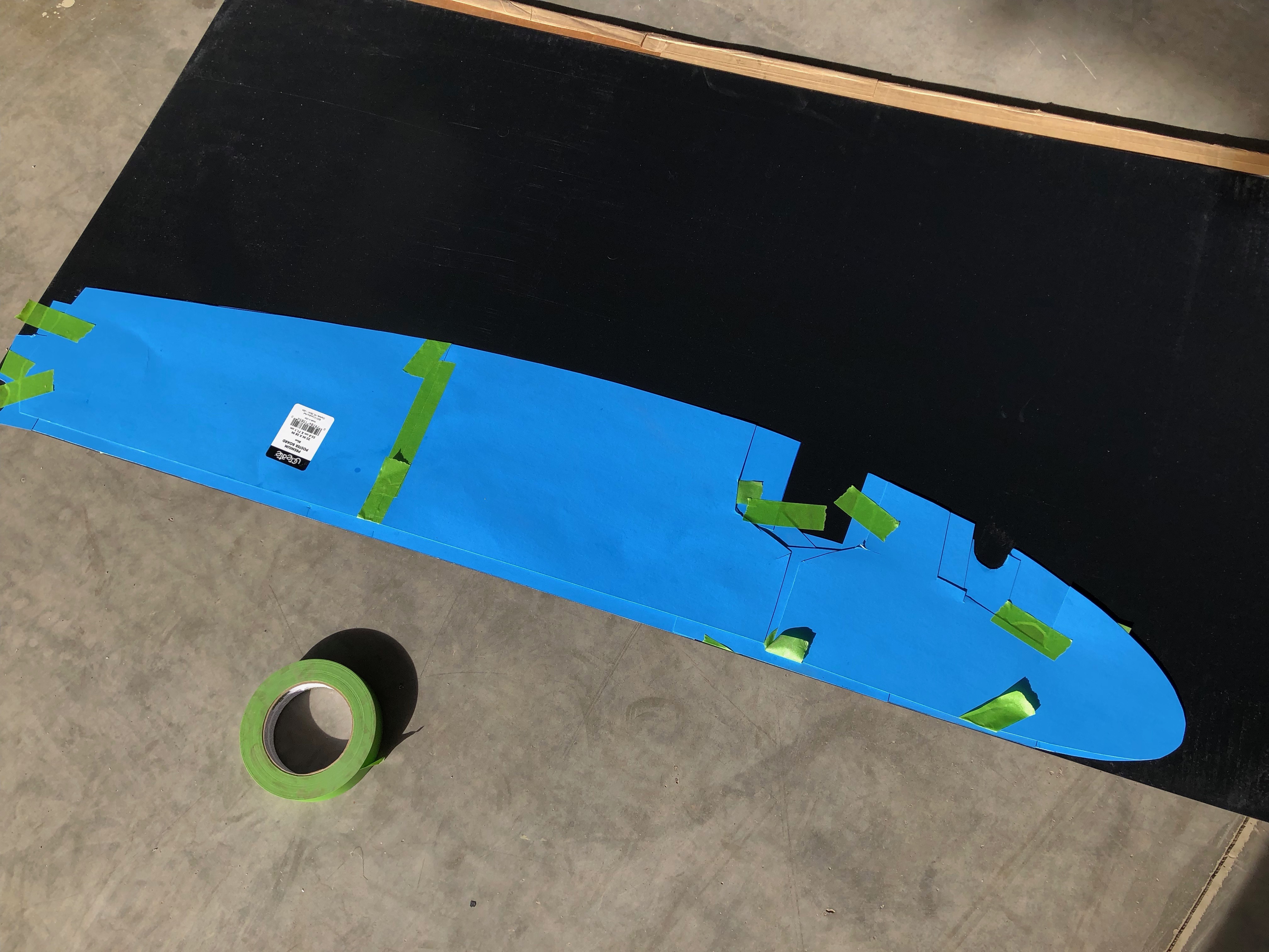
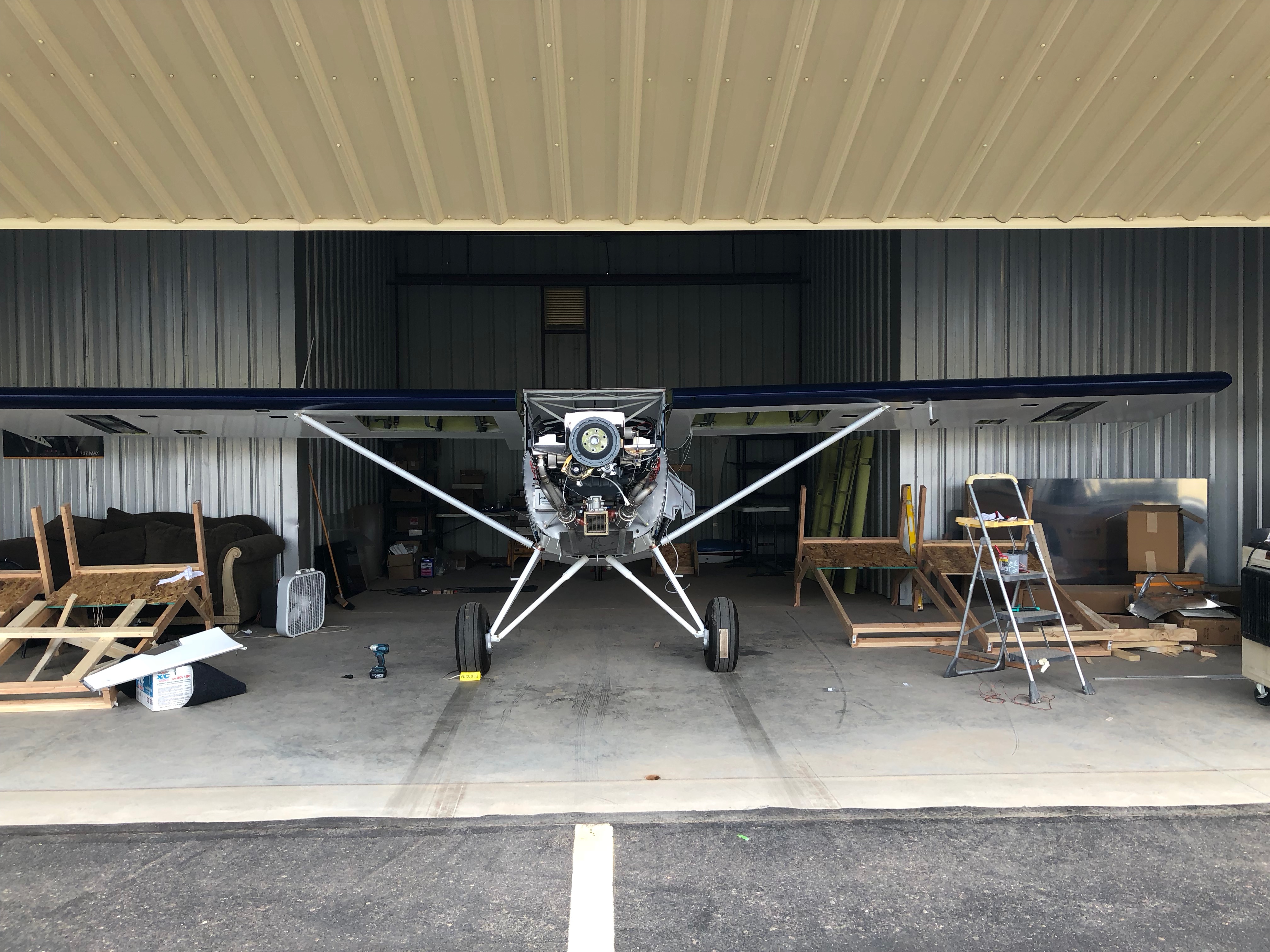
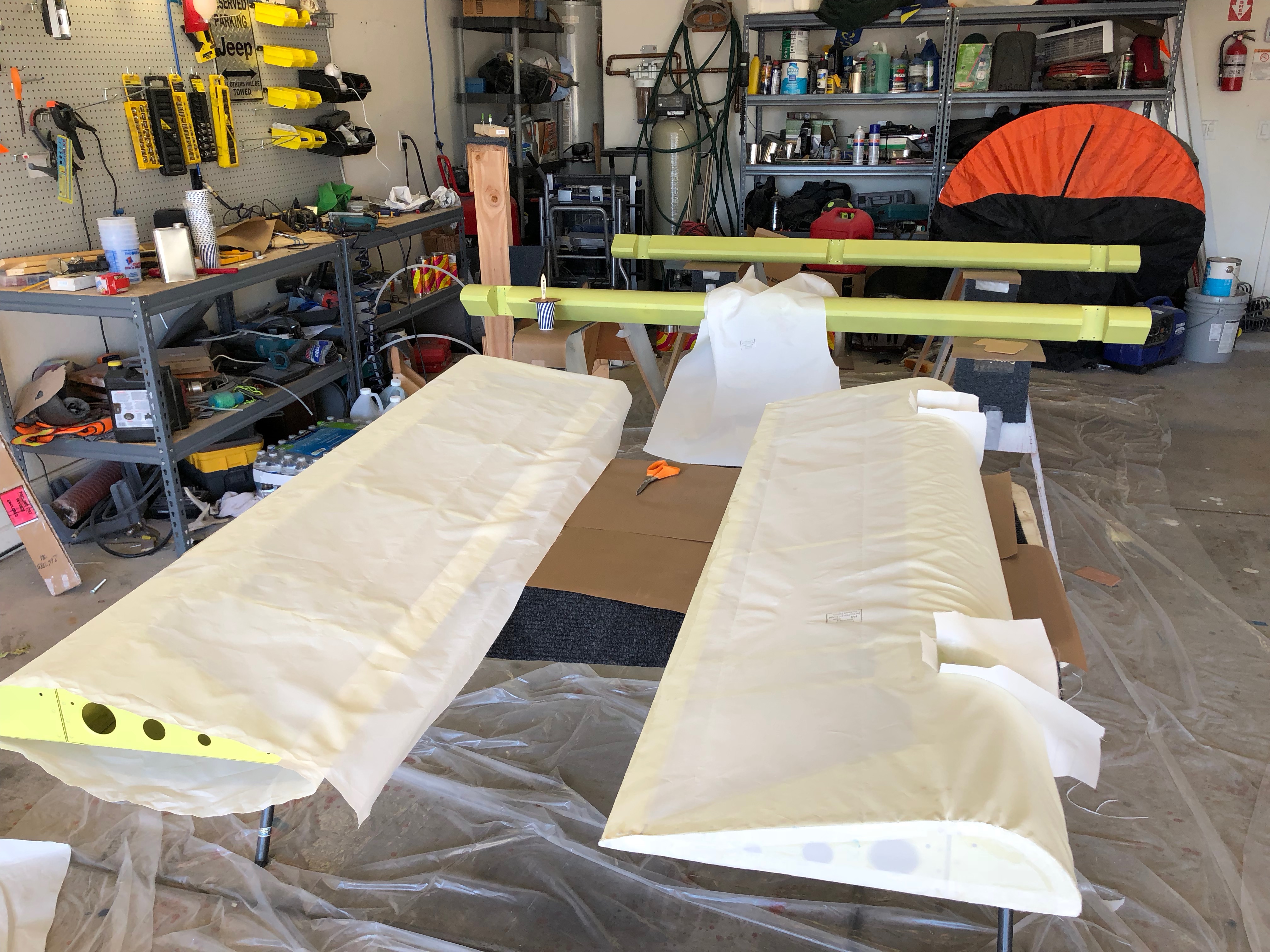
Taking a break from the airplane at the hangar I got to work on covering the ailerons and flaps. This is the exact same process as the rest of the fabric covering I’ve done so far.

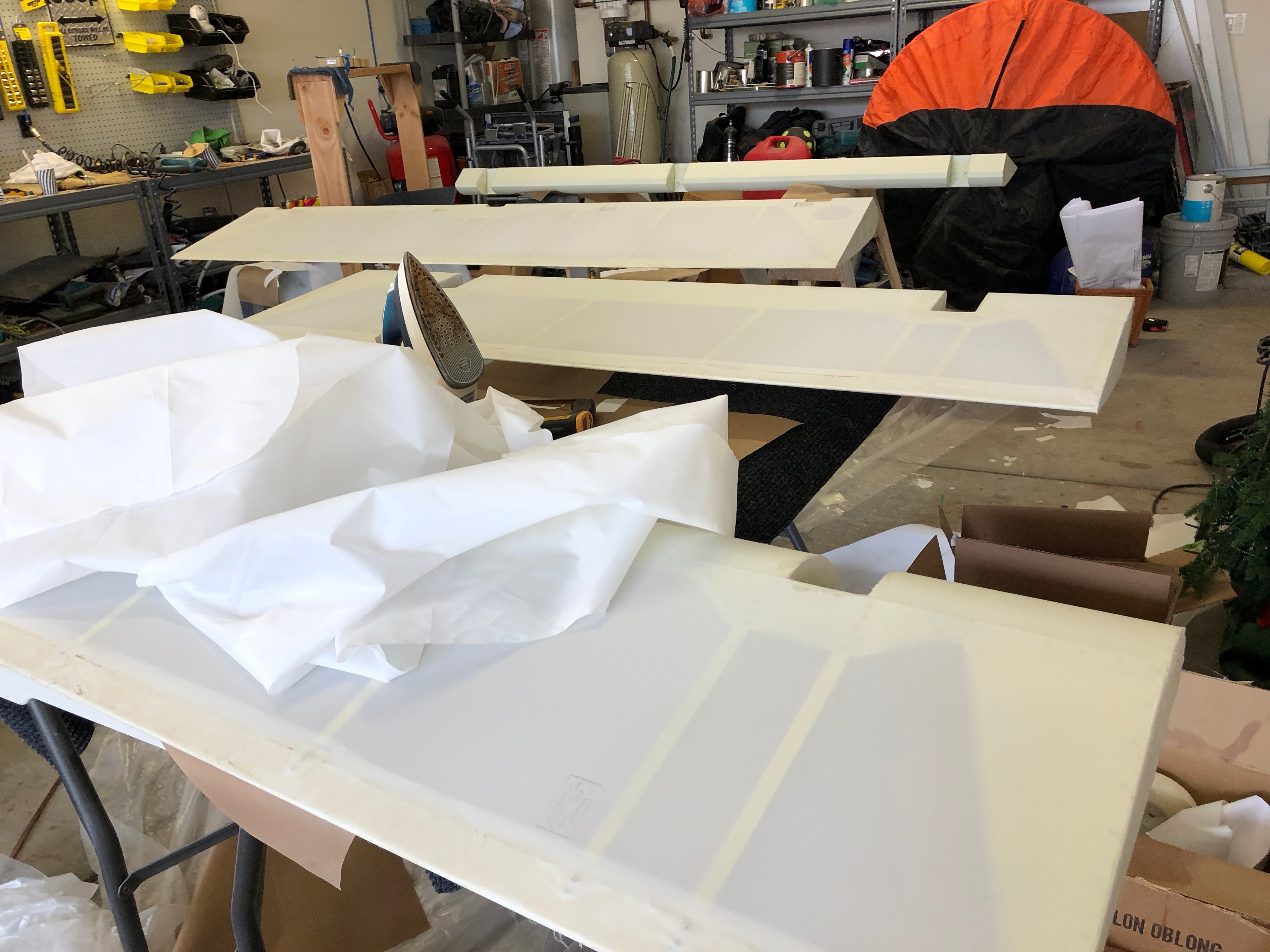
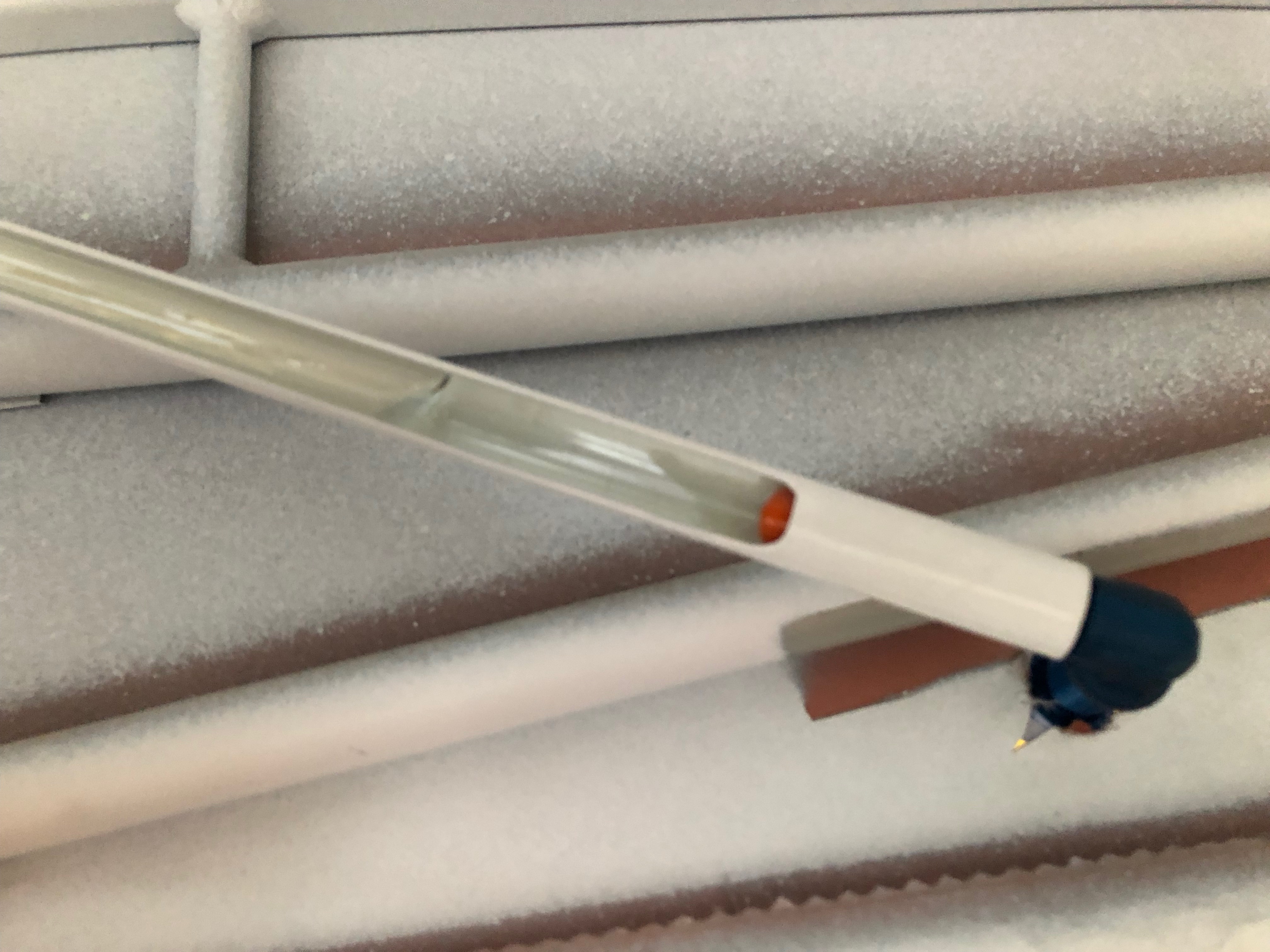
It’s always cool to see how the fabric tightens right up with the iron.

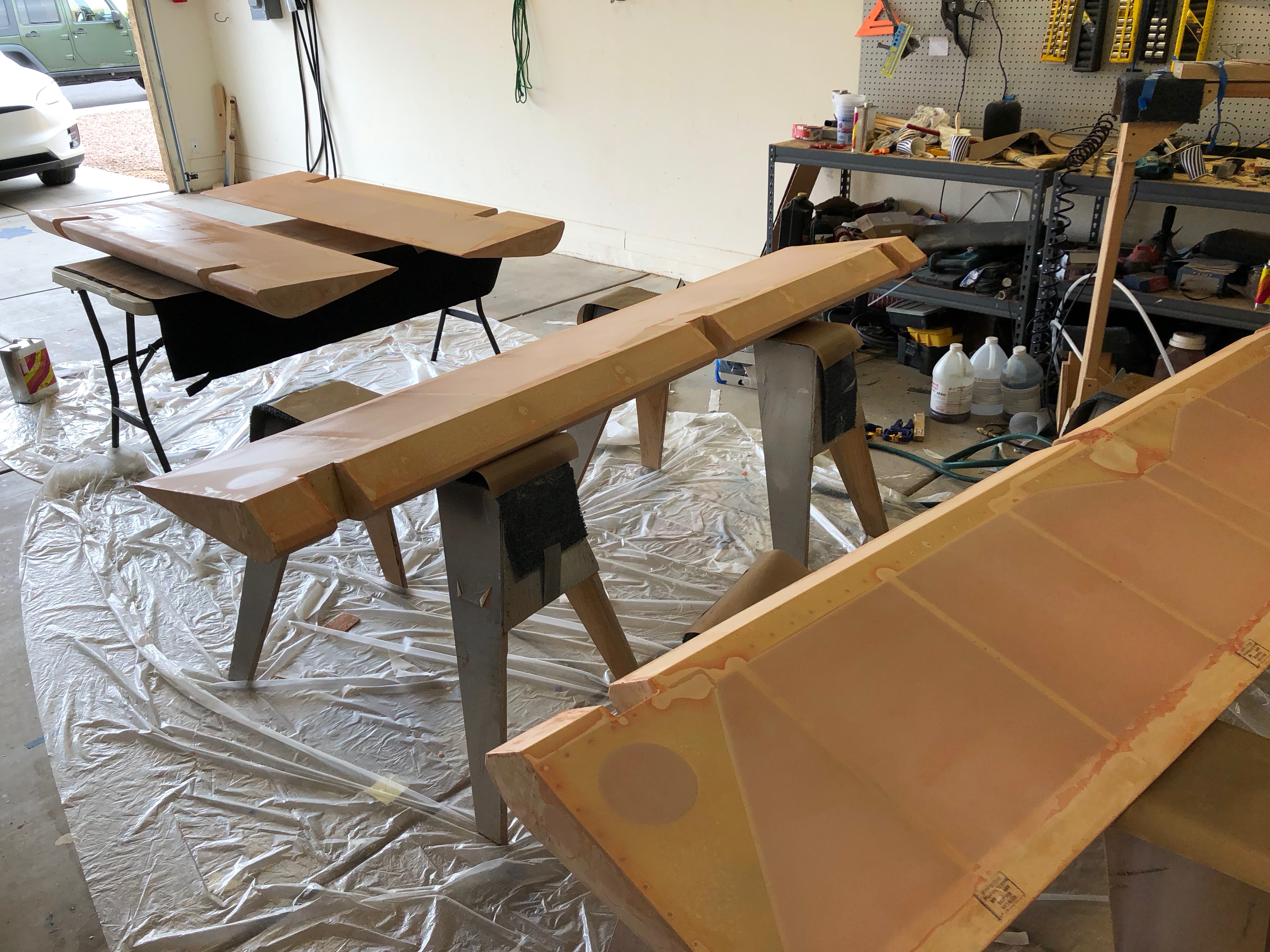
Making good progress they’re all polybushed and ready for rib stitching.

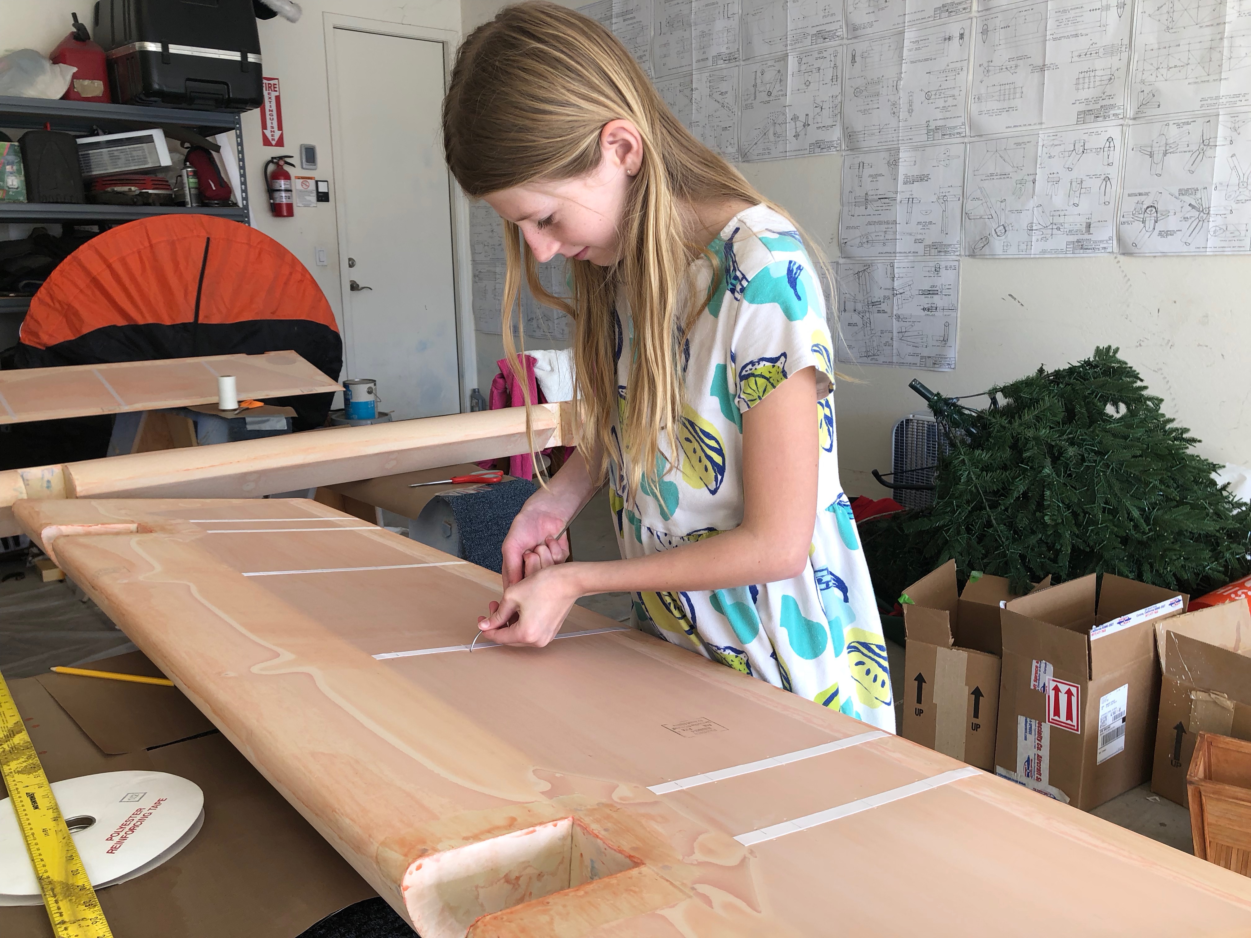
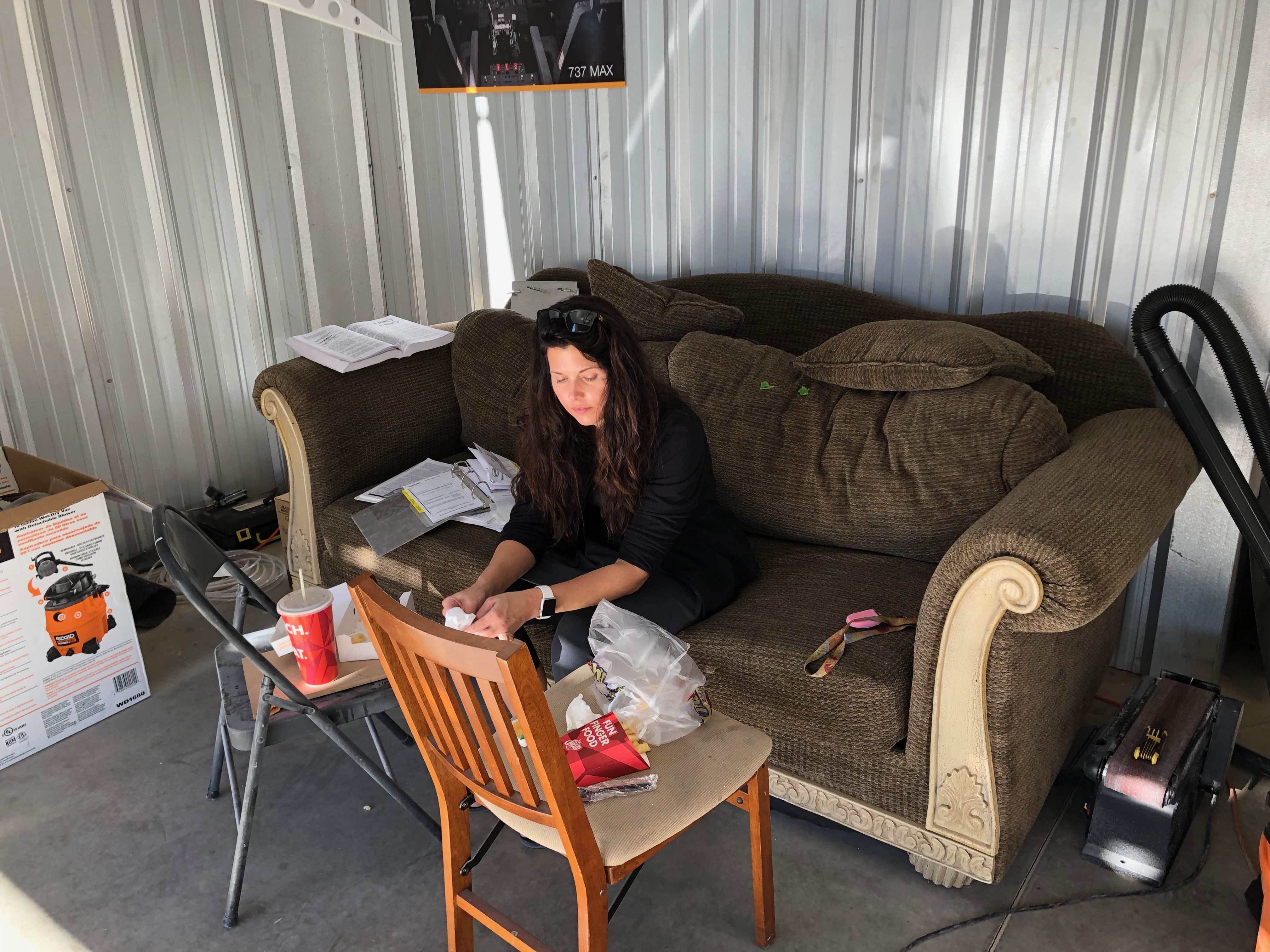
My trusty helper Tori came out to help poke holes and to chase the needle while I rib stitched.

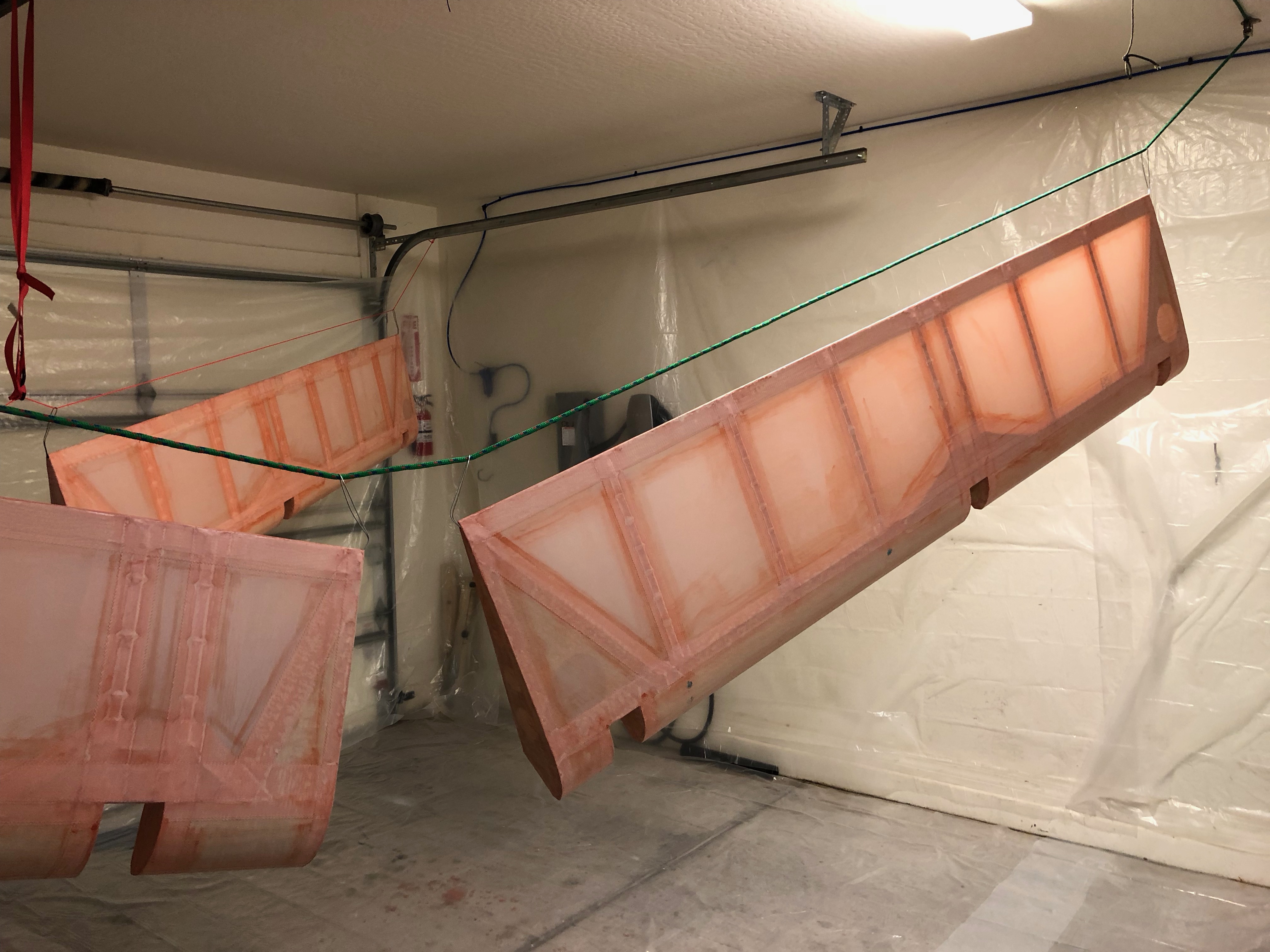
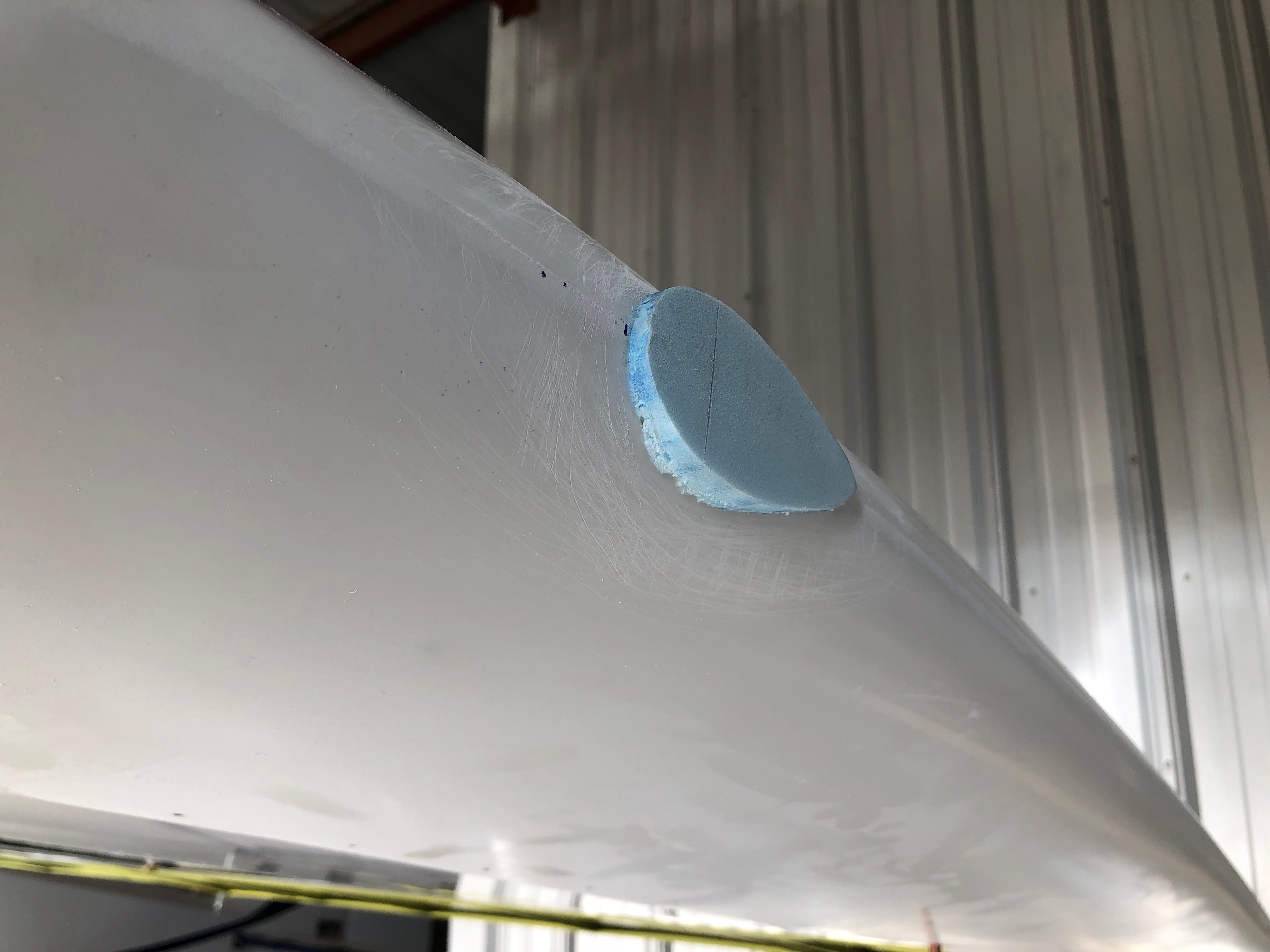
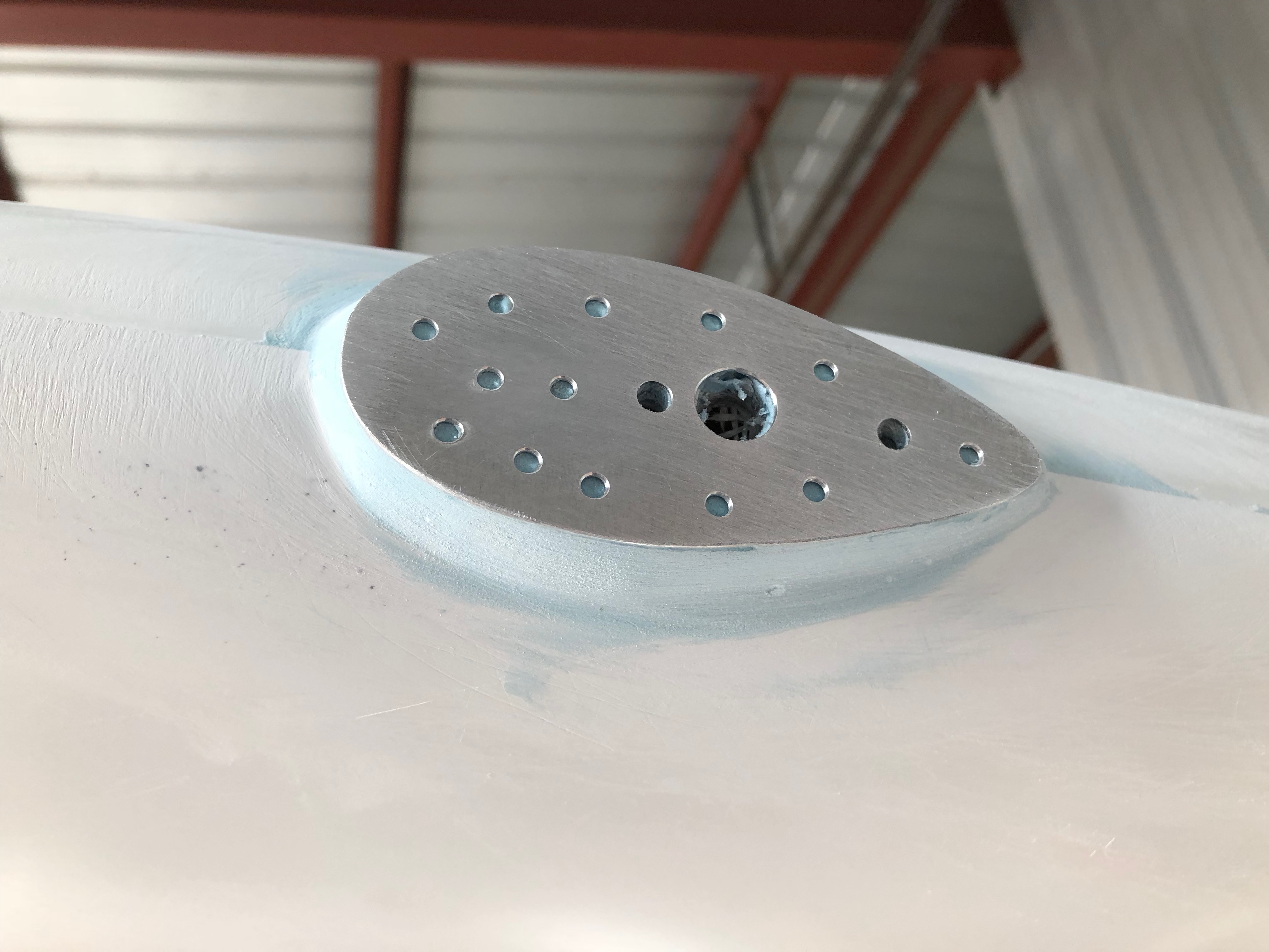
After finishing all the tapes, another paint booth was erected.  One coat in the morning and one in the evening through all the stages of PolyBrush, PolySpray and finally Poly Tone.

Wingtip light mounts

I need to make some mounts for the wingtip lights. So I traced the outline of the lights onto some aluminum.

I also made the same trace onto some fiberglassing foam and contoured it to the wing shape.

Here it is glued in place on the wingtip.

Then I glued the aluminum reinforcements onto the foam.  I put several holes in the aluminum to help the epoxy grip the aluminum.

Wingtips are short

After aligning the aileron and flap trailing edges to make sure they were straight and square, it because obvious that the wing tips weren’t long enough.

So I took some fiberglassing foam, created the proper shape and hot-glued it in place.

After some SuperFill to fill the gaps I sanded it all down to the proper shape in preparation for the actual fiberglass to cover it.

Ailerons and Flaps

After fitting the ailerons and flaps to the wings we marked the hinge bracket locations and drilled them to their respective control surface.  My friend Rusty came over and spent a day helping me drill all the nut plates for the brackets.  Then we riveted on the reinforcement strips.

Next came the counter weights.  I went to Ace and picked up some aluminum tube, then to Sportsmans Warehouse to pick up some #8 bird shot.  I created a slurry of JB weld and shot to make a plug in one end of the tube.  After curing, I alternated shot and epoxy until the tube was full to the top.  After a few small adjustments I got exactly the right weight.

Finally the airplane has all it’s flight controls.  Now on to aligning the trailing edges.


Windshield Fairing

Today my wife Cati showed up to help me make the fiberglass windshield fairing.        First we used packing tap the make the fairing shape between he boot cowl and the windshield.  Then we use mold release wax on the entire surface.

We cut the strips to the proper width and length.  Then Cati went to work on wetting the resin then squeezing the excess out on a table.  I took the strips and started laying them up on the windshield.  10 layers in all.

After curing for a day, I used masking tap the mark the edges.  Then used a band saw to trim it up.  Turned out much better than I would have imagined!

Cati is taking a well deserved break eating my lunch.  🙂

Interior Trim Panels

I once again used my arts and crafts skills to make pasteboard templates for the interior trim pieces.  Here is the wing root on the inside of the cabin.

Here is the wing root interior piece with the fuel sight gage with a new orange ball that actually floats this time!

Here are the interior pieces for the forward and lower cockpit.

Here is the top piece that Matt from Alaska made up for me.  You’d think these things would be easy to make, but it took a while!  Turned out great though and gives nice contrast.  It’s also very light.

Magneto trouble and an Alaskan visitor

Funny story.  Matt was visiting from Alaska and wanted to save on shipping for some heavy tools he ordered.  So he found me on the bear hawk forums and asked if he could have them shipped to my house so he could take them as checked luggage back to AK.  And a great friendship was born!

To say thanks for housing his tools for a while, he offered to stop by and help wrench on my Bearhawk.  We worked on a few odds and ends and he fabricated a few interior pieces.  But the bulk of our time was spent fiddling with the magnetos!

To begin with the internal gears weren’t clocked right so we had to re-clock them.  Then we found the impulse coupling was magnetized and wasn’t allowing the pawls to free fall.  Then the right mag had a bad grounding issue that was intermittent.  Matt was super patient and helped me noodle through these very perplexing issues.

After A LOT of fiddling, we finally decided to send off the left mag to have the impulse coupling replaced and deferred dealing with the right mag.  More on that to follow.  (Spoiler alert: I eventually went with electronic ignition on the right side).

Fuel indicators

I decided to make my own fuel indicator.  It was very easy and I recommend it.  Super light and no glass in the cockpit!

I bought these little balls that are supposed to float in the tube.  Wouldn’t you know it, it sank!  They’re a PMA part also!  So, I had to order more.  Oh well.

Finishing the seats

I’ve found that I don’t necessarily enjoy sewing.  However most of that is because I was using the wrong size needle for this leather.  I bought a needle designed for denim and it finally worked much better.

If I had it to over again, I’d do a much better job, but I don’t feel like doing it over!  🙂